
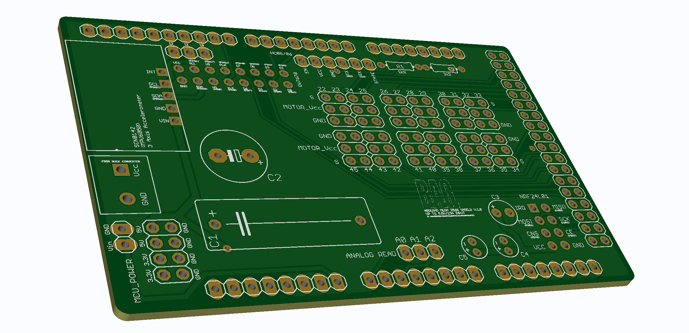
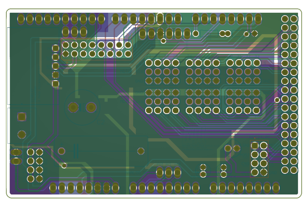
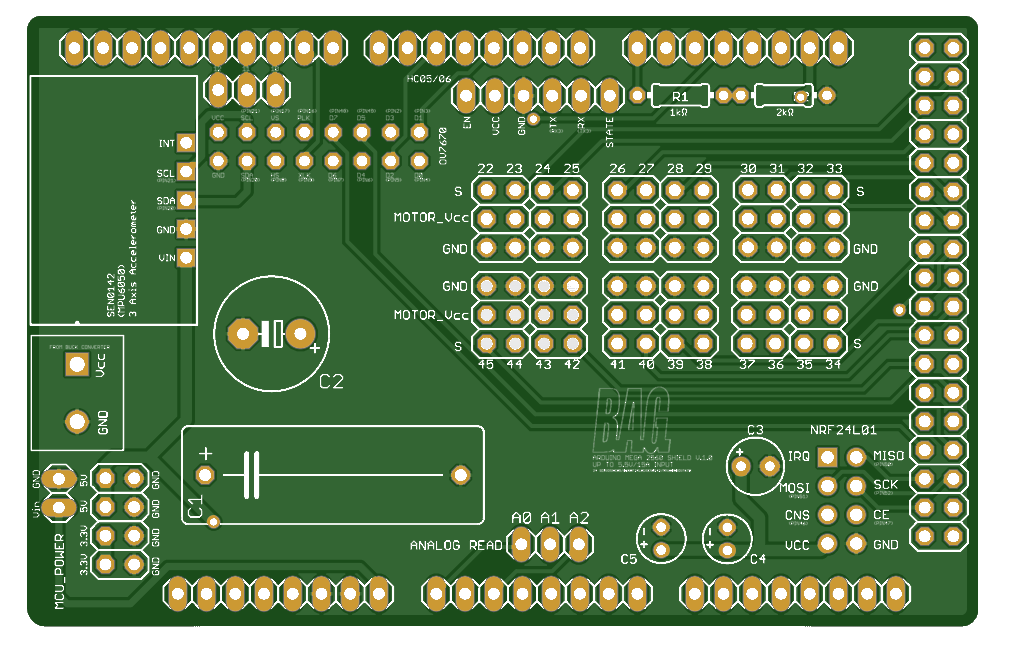

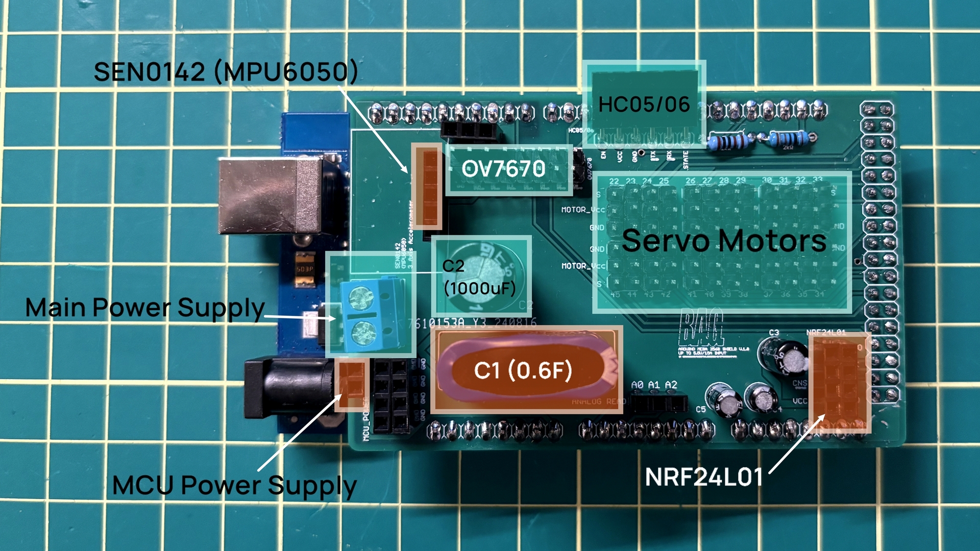
A fully customized 4-layers PCB for mechatronics DIY hobbyist that can support up to 24 servo motors, bluetooth/2.4GHz transceiver, gyroscope, and camera module. (Up to 7.5V/15A input)

It features

Assembly Guidance

To power 18 RDS3225 servo motors simultaneously while avoiding voltage drop issues, a large 0.6F capacitor was placed at C1, with a relatively smaller 1000µF capacitor placed in parallel at C2. 

Capacitors of 100µF, 10µF, and 0.1µF were placed at C3, C4, and C5 respectively. A 1kΩ resistor was placed at R1 and a 2kΩ resistor at R2 to create a voltage divider circuit, which reduces the voltage to around 3.3V for the RX pin of the HC05/06 module. For more details, please refer to the shared Gerber file below.

https://drive.google.com/drive/folders/17j_bDiwszHmci_YNZK1wv7SDB-q9JGdj?usp=sharing

Pin Definition

Below are the shield pins corresponding to the pins on the Arduino Mega2560:

Pin Correspond Arduino Pin Description
HC05/HC06
EN - -
VCC - Main power supply (shared with servo motors)
GND GND -
TX RX3 -
RX TX3 -
STATE - -
Servo Motor​ Pins
S PIN 22~45 -
MOTOR_Vcc - Main power supply (shared with HC05/HC06)
GND GND -
NRF24L01
IRQ - -
MOSI PIN 51 -
CNS PIN 46 -
VCC 3.3V PIN MCU provides the power
MISO PIN 50 -
SCK PIN 52 -
CE PIN 47 -
GND GND -
MCU_POWER
VIN - MCU power supply (separate power supply from the main power supply)
GND GND -
SEN0142(MPU6050)
INT - -
SCL PIN 21 -
SDA PIN 20 -
GND GND -
VIN 5V PIN MCU provides the power
OV7670
VCC 3.3V PIN MCU provides the power
SCL PIN 21 -
VS PIN 17 -
PLK PIN 16 -
D7 PIN 48 -
D5 PIN 49 -
D3 PIN 2 -
D1 PIN 3 -
D0 PIN 4 -
D2 PIN 5 -
D4 PIN 6 -
D6 PIN 7 -
XLK PIN 9 -
HS PIN 8 -
SDA PIN 20 -
GND GND -
Other Pins
3.3V 3.3V PIN -
5V 5V PIN -
12 PIN 12 -
11 PIN 11 -
10 PIN 10 -
A0 (Analog Read) A0 PIN -
A1 (Analog Read) A1 PIN -
A2 (Analog Read) A2 PIN -
C1 (+) - Connect to the main power supply
C2​ (+) - Connect to the main power supply
C3 ​(+) 3.3V PIN -
C4​ (+) 3.3V PIN -
C5​ (+) 3.3V PIN -